Skip to content

Authored by Michael Rakos, District Manager
ASNT PHILADELPHIA CHAPTER MEETING FEBRUARY 2012
Introduction
Magnetic Analysis Corporation, most commonly referred to as MAC, is a major worldwide source of NDT equipment including eddy current, flux leakage, and ultrasonic inspection systems. Since its beginnings to present day, MAC has been the first to market with various types of groundbreaking NDT equipment. These equipments range from the first successful encircling coil electromagnetic tester in the U.S. to the world’s first spinning probe eddy current tester. Various significant types of NDT equipment releases, by both MAC and others, will also be chronicled leading up to the present day. MAC has a long colorful history, and many interesting historical developments led up to its inception and development of product lines through history.
Magnetic Analysis Corporation was founded in 1928 in Long Island City, NY, USA, by William S. Gould and William S. Gould Jr. to develop a group of patents for nondestructive electromagnetic testing of steel bars. William S. Gould was a New York industrialist and former President of the Gould National Battery Company. These acquired patents dated from 1919 through 1928 and had been developed by a previous corporation known as the “Burrows Magnetic Equipment Corporation.” This predecessor company included several notable people, including Dr. Charles Burrows, a former physicist from the U.S. Bureau of Standards, Bradley Stoughton, a Professor of metallurgy at Lehigh University, and Elmer S. Imes, the second African American PhD physicist in the United States (1).
The term “Magnetic Analysis” was originated by Dr. Charles Burrows. He defined it as the investigation of the mechanical properties of a magnetic material exclusively through its magnetic properties. In 1917, Dr. Burrows presented a paper at the ASTM annual meeting entitled “Some Applications of Magnetic Analysis to the Study of Steel Products” (2). The railroad industry, including the Pennsylvania and New York Central, already had an interest, but now other steel-related industries were taking notice. His paper also attracted the attention of the scientific community, and the idea of testing the quality of steel through its magnetic properties began to be taken seriously. Many individuals became inspired to develop a successful electromagnetic tester, and a flurry of patents would soon follow, including those of Dr. Burrows.
Although successful laboratory experiments in electromagnetic testing began in the prior century, the application of electromagnetic test principles into viable equipment for the steel manufacturing industry remained elusive. This was the case prior to, and even for a short time after, MAC’s founding. At first, the equipment based on MAC’s purchased patents didn’t work as needed. After a few short years, and several new patents, persistence would eventually lead MAC in 1934 to the first successful Electromagnetic Tester in the United States (Fig. 1 on left shows the original logo for MAC).

Early Attempts at Practical Testing
The use of 1920s technology to develop practical high-speed electromagnetic testing was based on very basic fundamentals discovered in the prior century. The first known application of using the magnetic properties of a metal to locate flaws within it occurred in 1868. Lt. Stephen Martin Saxby of the British Royal Navy noticed unusual deflections of a compass needle when passed over a flaw. He first applied this technique to cannon barrels on ships in the Royal Navy dockyard (3).
Shortly after this discovery in 1877, Anaxamander Herring of Albany, New York, patented a similar technique in the U.S. for use on rail (4). He proposed that the rail should have current passed through it first to properly magnetize it. Charles Ryder of Cleveland, Ohio, was first in the U.S. to patent an apparatus for testing steel (5). The intent of his device was to measure carbon content, and this could be considered the first electromagnetic comparator. It used a compass needle in the center and a magnetized steel part on either side. One part was to be of known carbon content, and the other side was to be measured on the calibrated scale when the needle came to the centered position.
Two years later, Anaxamander Herring patented another apparatus intended for testing the tensile strength of steel wire or strip (6). His device first magnetized the material with an electromagnet and then used a gauss meter to measure the retained field strength as the material was spooled through.
The Influence of the Railroad
The railroad industry deserves much early credit for spawning the incentive to develop a viable high-speed electromagnetic test. Rail inspections were initially performed solely by visual means. Visual inspections at best only located external defects, and sometimes the subtle signs of large internal problems.
In 1911, the need for a better inspection method became a very high priority. A derailment occurred at Manchester, NY, in which 29 people were killed and 60 seriously injured. In the U.S. Bureau of Safety's (now the National Transportation Safety Board) investigation of the accident, a broken rail was determined to be the cause. The bureau established that the rail failure was caused by a defect that was entirely internal and probably could not have been detected by visual means. The defect was called a transverse fissure (example shown on the left in Fig. 2). In 1912, the railroads, in conjunction with the U.S. Bureau of Standards, began investigating the prevalence of this defect and found transverse fissures were widespread (7).

Involvement of the U.S. Bureau of Standards
In 1915, the Bureau of Standards, with Dr. Burrows, began experiments to develop magnetic testing equipment for locating and measuring transverse fissures in rails (7). Dr. Burrows first became interested in the relationship between electromagnetic and physical properties of steel in 1906 while managing the magnetic section of the U.S. Bureau of Standards in Washington (8). He gained early fame for inventing the “Burrows Permeameter” in 1909, and it became the standard instrument for measuring and classifying magnetic properties at the Bureau (9).
His original idea for high-speed testing was a simple flux leakage concept he later filed for a patent in 1917 (10). A winding encircled the bar in which a DC current was passed to create a magnetic field, and a separate pickup winding connected to a galvanometer would respond to the leakage field caused by changes in the steel bar. An inspector would then interpret the meter readings caused by the leakage field to identify flawed areas and hopefully estimate the severity.
At the Bureau of Standards laboratory, this equipment was successful in tests, but when adapted for actual tests on track, it was not able to differentiate actual defects in rails from the strains caused by slipping wheels, surface irregularities, and cold working by car wheels (7).

Burrows Magnetic Equipment Corporation
Charles Burrows resigned his post at the Bureau of Standards in 1918, and started his own research laboratory in the New York City area (11). His intent was to work on developing equipment to meet the needs of the steel industry and in particular, for testing steel bar. Being quite active in the ASTM, he was chosen in this same year to chair a newly formed committee called “committee A-8 on Magnetic Analysis” (12). His work soon became noticed by the Federated Engineers Development Corporation. They were comprised of noted engineers, scientists, and businessmen. Their purpose was to review hundreds of inventions and choose a few that they would promote (13). They had particular interest in Burrows work, and in 1924, the “Burrows Magnetic Equipment Corporation” was formed as a subsidiary. The aim was to design equipment for the steel industry that would prove workable in an industrial environment (8). Many prototype equipments were built, but the most promise for high speed inspection was developing his flux leakage tester patent (10) known as “Defectoscope” (as shown in fig.3). When MAC was formed several years later, the hope was that this equipment, for testing wire rope, rails, bar and strip, would be well received by the steel industry. However, the moving coil system, combined with its use of a fragile laboratory mirror galvanometer proved ill suited for the needs of the steel plants. These mirror galvanometers were used extensively in scientific instruments before reliable, stable amplifiers were available. A concave mirror attached to the pointer would reflect light onto a screen. This concave mirror was often knocked off the pointer needle from large signals and required repair. Viewing had to be done in a darkened area, usually by draping a tarp over the equipment. Several of these “Defectoscope” equipments were put into service by industry and government, and stayed in use for many years despite their shortcomings. Dr. Burrows succeeded in demonstrating the feasibility of indicating large discontinuities in steel by measuring changes in permeability (permeability is the relative ability of the material to pass magnetic lines of force). Normal variations in permeability of most steel however, produced extreme swings in the readings such that the detection of small and moderate defects was not really possible. Charles Burrows fiercely believed only one set of mechanical characteristics correlated to a given set of magnetic characteristics, and much of his equipment reflected that concept. He had a multitude of interesting patents throughout the 1920’s, most of which were founded in solid theory, but in practice did not provide the accuracy or high speed testing required by the manufacturing industry. The tester shown in Figure 4 (14) applied a rotating magnetic field on a part such as a bearing race, and measured the mechanical force to which the part was attracted in this field. A second version using three phase AC was also designed.

A portable flux leakage plate tester (fig.5) was also an invention of Charles Burrows (15). It incorporated a marking system to spray paint on defective areas. Although this version never saw service, the patent offered some protection to MAC in the 1989 release of its TBT I Aboveground Tank bottom tester.

Sperry Develops Successful Rail Testing
In 1923, Dr. Elmer Sperry, started to develop and build a rail inspection car with the capability of detecting transverse fissures in railroad rails. In 1927 Sperry built an inspection car under contract with the American Railway Association. A small flatbed in front of the cab contained the inspection equipment. The operator and recording devices were housed in the cab. His original design energized the rail with current and measured variations in potential drop by means of a pair of contacts. The average conditions of the surface of the rail prevented continuous contact of the searching units with the rail, and caused many false indications. Extensive research was continued to develop a practical means of cleaning the rail before testing, but no solution was found and the method was abandoned (16). Shortly afterward in 1928, Sperry and his engineers successfully adapted the Burrows flux leakage method, combined with Herring’s manual technique for rail testing 50 years before. Instead of inducing a magnetic field by means of an external coil, contact brushes passed a large current through the rail to set up the field. The sensing coil would pick up leakage field around transverse defects as the testing car sped along. He called this the “Induction method” and it is shown on the left in figure 6.

MAC is Founded
After MAC’s acquisition of the Burrows patents in 1928, much effort was put into making them work for practical applications. The design shown in figure 7 (17) by Burrows, is a modified Induction Balance. David E. Hughes experimented with a similar circuit in 1879 for investigating the conductivity of metals (18), and it would later be applied in metal detectors. The system consisted of two identical transformer like primary and secondary coil windings at each end of the device, with the secondaries inductively opposing one another. These windings know as “coils” encircled the bar, with the secondary winding being closest to the bar, and the primary coil wound on top of the electrically insulated secondary. One coil would be chosen as the reference, and would contain a standard bar for all others to be measured against, and not to be moved.
The other coil would be for testing, and the bars to be inspected would be continually passed through it. Any change in the magnetic properties of the test bar should be observed by a meter deflection. This basic theory is sound, and is the basis for all modern comparators today. However, there were too many practical problems for this basic circuit to work effectively, namely the difficulty in making two coils precisely impedance matched. Many modifications of this induction balance system would be explored by MAC before it worked effectively.
Dr. Theodor Zuschlag Joins MAC
In 1931, Dr. Theodore Zuschlag, a native of Germany, became Chief Engineer of MAC. He successfully developed the work of Dr. Burrows who had died shortly after the company’s founding (19). Dr. Zuschlag emigrated in 1925, and immediately started work for the Taumac Corporation out of New York developing electromagnetic prospecting techniques (20). He filed several patents for using magnetic fields to locate subsurface mineral deposits, and he had a very good understanding of the challenges facing the fledgling MAC. He quickly refined the work of Burrows into MAC’s first successful tester. The principal discovery he patented was a proper balance compensation of the secondary coils using a bridge network (fig.7) (21). This enabled adjustment to zero out any differences in the system which was always a problem in the past. Slight variations in test coils, materials, or stray fields no longer posed a problem. He also invented a novel technique for analyzing phase shift of wave forms without an oscilloscope. It used a synchronous motor driving a mechanical rectifier and could read phase shifts using two galvanometers. He recognized at the time the early oscilloscope displays were small and difficult to use, as well as too fragile for most environments MAC needed to operate in. He patented this technique for use in other applications, even one using a rotating neon tube known as a Neoscope (22). He later refined the technique using mixing transformers instead of moving parts.

First Successful Electromagnetic Tester to Identify Cracks in Steel Bars
Finally in 1934, MAC introduced their first successful electromagnetic tester to identify cracks in steel bars. It was housed in a wooden cabinet, and at first was met with considerable skepticism from early customers. But MAC believed so strongly in this tester that they offered this equipment on a lease basis so the customer would not have to make a capital investment. With this incentive, in 1934 Union Drawn Steel of Hartford, CT, (which is now part of Republic Steel) became the first company to install a MAC electromagnetic tester. MAC's concept of an operating lease for NDT equipment combined with highly skilled field staff soon became a successful part of MAC's marketing program, one that remains to this day. This equipment featured Dr. Theodore Zuschlag’s coil balance compensation circuit, and specially arranged test coils at each end of the device with a several inch air gap in between, instead of putting one offline with a known good bar inserted. This novel technique in effect, “nulled” out changes caused by temperature and other local variations in the same bar being tested that may have otherwise caused defect-like indications. A 60Hz AC current energized the two primary coils, and changes in the bar’s permeability directly under each of the secondary coils would translate to an impedance change in the secondary circuit, and deflect a galvanometer. One of the most important contributions of Dr. Zuschlag was the differential or “null” secondary winding (23). He combined the two separate coils of the first-generation tester into one, such that they shared the same primary. It enabled finding very short flaws at high speeds, and is at the foundation of the test coils used today with modern eddy current equipment. The coil pictured in figure 8 was about two feet in length and had an interchangeable core on which the secondary coils were wound. This enabled the use of different sizes to reduce the air gap between the material and the test coil (known as fill factor). This coil also had an absolute winding, as well as end-sensing windings to be used in conjunction with an end suppression circuit.
With the success of the first tester, research on electromagnetic testing continued at MAC and Republic Steel in the United States. Dr. Zuschlag refined the test methods he had developed, introducing improved balancing and phase analysis circuits. This equipment utilized the patented test coil and could test at speeds up to 200ft/min. A flaw detection circuit would now illuminate an indicator on the instrument when a defect passed by (23). This eliminated the need for the operator to concentrate his gaze on a meter, which may have responded quickly, or not at all for short flaws at high speed. This equipment was called a “Dual Method” since an absolute test was also employed to sort bars on alloy or to find long continuous defects. This method could be used by itself or at the same time as the null test, but required the observation of two meters for amplitude differences or phase shift. Another important feature of this equipment was end suppression, which prevented false indications as front and back ends came through the test coil.

Republic Steel Develops Saturation Technique
While MAC was perfecting its permeability test, Republic Steel (which had their own research facility in Ohio) had some major breakthroughs in eddy current testing. They were the first to patent a DC saturation technique in 1936 to eliminate the effects of permeability (24). This allowed steel to be examined by eddy currents for changes exclusively in conductivity, and enabled inspection of soft annealed or hot rolled bar and tubes. A higher frequency of 500Hz was required to get enough eddy currents on the surface to see a defect. This equipment and method, sometimes referred to as a “Farrowtest,” was named for the inventor Cecil Farrow, who developed it along with Horace Knerr and Archie Black. This equipment was not without its problems, the expensive coil system required immersion in oil much like a transformer to keep it cool. It was never marketed commercially or used outside of Republic Steel. MAC equipment was still used by Republic during this period, and a friendly relationship was maintained.
MAC Refines Electromagnetic Testing
Without saturation capability for the next twenty years because of the Republic patent, MAC put much effort into educating the steel industry about the science behind a successful electromagnetic test. Dr. Zuschlag was very involved in many industry organizations, and published an ASTM bulletin in 1939 about the history of electromagnetic testing technology up to that date, as well as dealing with the practical problems encountered while electromagnetic testing. He learned successful detection of flaws was a function of residual stresses in the material under test. An abrupt change in strain along the length greatly affected the magnetic properties at that same point in the bar and could be seen as a defect, or in some cases, mask one. Since the success of the test depended upon the changes in stress in the adjacent area of the flaw, he concluded that heat treated, cold drawn and machine straightened material would be most efficient for the detection of flaws (25). This created a clean uniform stress along the length, resulting in barely noticeable needle deflections on acceptable bar, and significant jumps in the presence of a tiny crack. Although the relationship between mechanical and magnetic properties of steel was more complex than that which Charles Burrows theorized, these observations of Dr. Zuschlag considerably improved test results of MAC customers.
With the entry of the U.S. into World War II, demand for electromagnetic testing equipment to inspect steel bars increased sharply. A U.S. Government requirement was enacted that all steel used in artillery shells had to be tested. In a two page advertisement in TIME magazine in June, 1940(fig. 9), Jones and Laughlin Steel Corporation of Pittsburgh, PA, featured MAC’s electromagnetic tester, and described the merits of this test method for inspecting cold finished steel bars for cracks. With better technology available, MAC introduced the “Multimethod” tester in 1944. It brought all the features of the Dual Method, but with improved testing capability. It used a large capacitor bank to improve power transfer to drive the test coil. On later models, it incorporated an oscilloscope display, and quickly became the workhorse of the steel industry, staying in service for many years.
 (Figure 9)
Following the end of WWII, MAC introduced a 60Hz comparator in 1949. The first equipment release was called model “849”. These instruments specialized in comparing various shaped steel parts with ones of known quality for grade and hardness. This broadened MAC’s Market to help offset the decline in demand for its bar tester after the war. The test coils could be made into rectangular shapes that fit the product to be tested. One of the first comparators was used at a bearing manufacturer named Hyatt to check heat treatment. Pratt and Whitney was also an early customer, using it to check steam turbine blades. These comparators were noted for their longevity, and it is interesting to note MAC is still using, as of this date, an original 849 comparator in its test department to quality check test coils.
 (Figure 10)
MAC also continued its flux leakage product line through its early years, and offered a wire rope tester. This equipment worked quite well, and was updated with newer technology through the years. Unfortunately this never became a large market for MAC; few requirements for inspection of wire rope were ever in place. It first saw service in a New Jersey Roebling Wire Works facility during WWII. Another reason the industry was reluctant to implement such equipment was it had to compete with the less expensive flour sack test, where a broken outside strand would tear it open.
Eddy Current Testing Comes of Age
In the latter 1940’s Dr. Zuschlag turned his attention to eddy current analysis of conductivity changes in non-magnetic metals. He also started working on saturation techniques MAC would later employ for steel products, learning from the experiences of Republic Steel. During this period after the war, Dr. Zuschlag had correspondence with Dr. Friedrich Forster, who was a fellow alumnus of the University of Goettingen. Dr. Forster is credited with developing early eddy current theories, and founded his company in 1948. A brief relationship existed while Dr. Forster was founding his company, but in 1952, Dr. Zuschlag died tragically at the age of 56 (19). Both MAC and Foerster Corporation would later compete with one another in the eddy current equipment world market, a competition that still exists today.
With the advent of the Korean conflict, demand for equipment to inspect steel bar once again surged, and MAC devoted its increased cash flow to still broader research. In 1953, under the direction of Joe Callan, who became the new Chief Engineer, MAC introduced the first commercial eddy current tester manufactured in the United States. Joe Callan joined MAC in 1946, and brought with him experience of developing radar systems for the Navy, as well as a metallurgical background from Crucible Steel Company. MAC’s first eddy current flaw tester was known as the M.A.S.E. (Magnetic Analysis Special Equipment). Unlike the first electromagnetic system, which measured permeability changes in magnetic materials, this new eddy current technology measured the change in a material's conductivity. This led to a more reliable inspection for short surface defects, and vastly expanded the market for MAC allowing non-ferrous metals such as copper, brass, stainless steel and aluminum to be inspected. An oscilloscope was used for a display, with a Lissajous curve signal pattern for defect interpretation. It operated at a fixed test frequency of 67 KHz. An interesting reason for this exact frequency choice had to do with avoiding the frequency of a local AM radio station out of Long Island, NY, at the time, which was causing interference in the detection circuits during development. The M.A.S.E. had immediate interest by welded stainless tube manufacturers, such as Carpenter Technologies, to find weld defects. With Republic Steel’s patent on DC saturation expiring in the late 1950’s MAC applied its newer generation of eddy current equipment to steel. This second generation of eddy current equipment for MAC was known as the SF, or Single Frequency (fig.12). By comparison, these new testers were much simpler to set up than the earlier electromagnetic permeability testers. The SF featured an oscilloscope with polar display. This was a major advancement, and is still used in MAC equipment today. Phase and amplitude of defect and noise signals could be read directly, and defect signals could be adjusted and rotated to trip a horizontal line threshold called a chord. Material that is free of anomalies would be represented by a stable dot in the center of the screen. Most of MAC’s steel manufacturing customers embraced this new way of testing. However, a few reluctant steel plants with skilled operators swore by the old methods, and held on to their Multimethods into the 1990’s.
 (Figure 11)
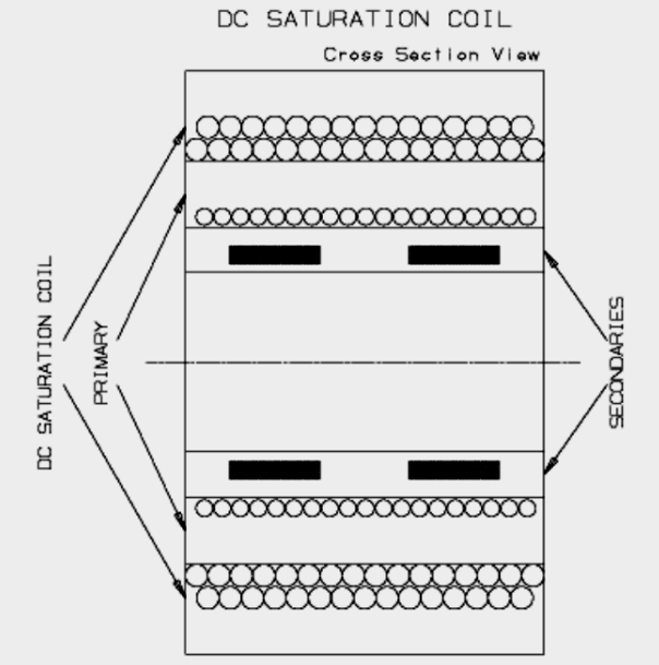
MAC’s DC saturation test system featured many improvements over Republic’s original design, and was built to take abuse. An air or water cooled electromagnet is permanently mounted inside a housing assembly which accepts different sized test coils (fig. 11). The assembly has vertical and horizontal adjustments for centering, and can pivot out of the way for coil changes. The original design had worked so well, very few improvements were needed through the years.
First Services for On-Site Probing of Heat Exchanger Vessel Tubes
Shell Oil Company’s research and development division deserves credit for developing the first eddy current probing equipment for the inside of tubing, with its patent in 1951 (26). It featured an automated probe puller and paper strip chart for a display. This equipment, originally called the “Probolog”, was very limited in its use and capabilities. It wasn’t until 1964 that Shell licensed Branson Instruments to manufacture and sell the Probolog, a name Branson later trademarked.
With the advanced features and rugged reliability of the SF eddy current tester, MAC developed a null ID probe for testing tubes inside heat exchanging equipment on site, in 1965. MAC would provide the equipment and conduct the test with its experienced field staff (fig.12). MAC’s testing proved invaluable, and demand for this testing surged, leading to further advances. Other probing equipment makers, such as Zetec, would later form, capitalizing on this growing business. By 1976, MAC also patented a novel technique for probing magnetic tubes (27). MAC engineer Bob Brooks used pulses to simultaneously provide saturation and test capability, without getting stuck inside magnetic tubes. With the probing business escalating and the equipment cumbersome to carry around, MAC packaged its probing equipment into a portable case in 1980, enabling testing on site anywhere in the world.
 (Figure 12)
World's First Spinning Probe Rotary Eddy Current Tester
In 1959, MAC launched the world's first spinning probe eddy current tester. It was an innovative solution to the problem of detecting long, continuous defects in wire and bar. MAC’s Chief Engineer Joe Callan and research engineer Edward Spierer were instrumental in this major development. The original probe used an absolute method, and worked quite well, especially once differentiator circuits were employed to emphasize signals with a large rate of change, such as a seam. In 1975, the null probe was patented, which gave even greater sensitivity to small defects (28). The probes are mounted on what is called a “headplate”. This standard version shown in figure 13 enables the probes to pivot. Counterweights on the end force the probes closed when spinning. The signals are transferred from probes through a rotating transformer. The original version was wound on a plastic type material called Bakelite. It was soon discovered the use of ferrite core rotary transformers enabled much higher test frequencies to be used. As testing capabilities improved, MAC Rotaries found use in many unique applications for finished parts such as Sachs strut rods, and Marlin rifle barrels.
 (Figure 13)
Today MAC rotaries can be made larger, operate at much higher speeds, and are capable of finding much smaller defects. In 2002 MAC was first to offer a rotary tester for hot wire. One such test system is successfully detecting long continuous defects in hot wire during production in a key Scandinavian steel hot mill.
Introduction of Solid State Electronics
In 1966, MAC moved into a new plant in Mt. Vernon NY., a place it would call home for the next 45 years. A year later a major advancement occurred with Research Engineer Sven Mannson in the launch of the ERIC (Extended Range Indicator Console) tester line. It was MAC’s first equipment to use solid state electronics, and featured phase gating and extended range filtering. The ERIC line became the flagship equipment for MAC through the 1970’s and 80’s. Higher test frequencies, signal distortion techniques, and automatic balancing circuits were introduced on subsequent ERIC II and III and IV releases.
 (Figure 14)
With the use of solid state electronics MAC was able to introduce the Varimac® line of comparators in 1967. This equipment would meet the need of a booming automotive parts industry at this time. It was designed to test parts at very high speeds, and had a variable test frequency. Applications included sorting different types of metals for many different reasons, such as alloy, grade, hardness, processing variations, some dimensions, and certain types of cracks in metal bar, tube, or parts. The parts would then be separated after test by fast acting solenoids known as a Parts Gate (fig. 14).
Today, after several generations of comparators, MAC has the Varimac VI, also used for high speed sorting of parts such as fasteners and bearings. Peak signal detection allows parts to be represented on the screen as dots plotted on an X-Y axis. When used with MAC's Parts Gates, parts can be sorted and counted at speeds up to six parts per second into three separate groups. MAC also still offers a powerful low frequency comparator called a PCVI, currently the sixth generation since its initial release in 1949. It checks case depth, core hardness, alloy and structure in ferromagnetic tube or bar at production line speeds, on line or off line. It is also capable of three way sorting of magnetic parts automatically with MAC’s automated Parts Gates.
Modern Applications of Flux Leakage Testing
During the early 1970’s oil crisis, MAC had seen a demand for high speed inspection of large diameter steel pipe used in the oil industry all over the world. To meet this need, MAC had applied its far reaching history of flux leakage with the experience of rotating probes, and by 1975 had introduced the first Rotary longitudinal Flux Leakage Tester (fig. 15). Demand for this type of test resurfaced in recent years, and in 2007, MAC developed a rotary transverse flux leakage flaw detector rotary. Using both rotaries, longitudinal and transverse, defects as small as 5% on OD, and 5% on ID, depending on material type and condition, can be detected.
 (Figure 15)
With the cold war still in play, in 1982 MAC started designing and building complex multi-test systems to inspect military ordnance. This included grenades, shell bodies, and aluminum shell bases. Several systems were bought by the U.S. Government. A system used at Picatinny Arsenal in New Jersey tested M42 grenades in storage from the Korean War era. This grenade is typically used inside the 155mm howitzer shell. The M42 grenade shell bodies contained internal embossing for fragmentation, and needed to be rejected if cracked. The flux leakage proved to be a safe way to test these grenades since they were live ammunition, and capable of explosion during testing. On a later built machine, eddy current comparator probes were used to check these M42 grenade shell bodies for missing fragmentation embossment before assembly.
In 1989, MAC released its TBT I Tank Bottom tester which used a rotary scanning flux leakage unit to detect corrosion in aboveground storage tanks. This tester was refined throughout the 1990's, leading to a third generation called TBT III which used both spinning flux leakage and eddy current probes. This technique gave better surface flaw detection, and discrimination between surface and subsurface defects. . Overall size and weight were reduced for better portability and ease of fitting through small access openings in above ground fuel storage tanks. This tester is capable of finding a 0.075” deep 1/8” diameter flat bottom hole on a 3/8” thick tank bottom. Unfortunately, the industry never required a 100% inspection of tank bottoms, and sampling techniques remain the cheaper and faster alternative. A flux leakage NDT equipment maker out of the UK named Silverwing notified MAC of their concern that their product was being copied but quickly dropped the matter when the original 1931 patent was presented (29).
MAC Diversifies into Rotary Ultrasonic Testing
In 1978, MAC signed an agreement with NUKEM GmbH in Germany. The rotary ultrasonic test systems developed by NUKEM for tubing and bar inspection were of high quality and cost, but they found many applications in North American markets. MAC continued as NUKEM’s sales agent with a brief interruption in the mid 1980’s, until early 1994. Beginning in 1989, MAC introduced its own line of Echomac® ultrasonic rotary testers for tube and bar, followed by the addition of the Echomac® FD instrumentation series, now the premier ultrasonic electronics. These original ultrasonic rotaries used a capacitor for signal transfer across the rotating head much like the NUKEMs. Today, MAC’s rotaries (fig. 16) use a rotary transformer for signal transfer which suppresses much of the high frequency noise that was a problem in the past with capacitors. The pulser and receiver are mounted on the rotating head for maximum sensitivity. Models are available for inspecting material from 50 mm to 220 mm in diameter at test speeds up to 200 fpm, depending on the size and condition of the material.
 (Figure 16)
First Fully Computer based eddy current tester
In 1992, MAC was first to introduce a fully computerized eddy current tester. It was a new benchmark for the industry, and provided an early foundation of learning which enabled MAC to stay far ahead of the competition to the present. Today, MAC has combined its rotary and coil eddy current instrumentation into a single equipment called the “Multimac®” (fig. 17). It brings along all of the best features of previous generation equipments, with the latest technology.
 (Figure 17)
MAC Today
Today, MAC has a strong worldwide presence. Since the 1960's under the leadership of William S. Gould III, MAC successfully expanded overseas, introducing test systems to Europe and Australia. The first equipment in Europe was installed at British Timken by MAC's United Kingdom subsidiary in 1962. Other subsidiaries were established in Italy, Australia, Sweden, and manufacturing operations were expanded with the opening of a plant in Ohio in 1975 and in Sweden in 2000. MAC also has a Representative Office in Shanghai China, representatives in Russia, South Korea, India, Mexico, and various other locations throughout Europe and South America. In the U.S., MAC still has one of the most extensive and experienced NDT field staff.
 (Figure 18)
After more than 40 years in Mount Vernon, New York, MAC relocated to a larger plant at 103 Fairview Park Drive in Elmsford, New York at the end of 2010 (fig. 18). The new facility increases MAC’s floor space by 80%, greatly expanding the ability to manufacture and assemble large inspection systems, and demonstrate them for customers. These systems include Eddy Current, Ultrasonic, Flux Leakage, Multiple and custom designed systems, and systems for material handling. MAC remains committed to research and development, and harbors a highly skilled engineering department. We look forward to enduring as a leader by meeting the needs of an ever changing NDT market.
Works Cited
- This Month in Physics History, November 1919: Elmer Imes Publishes Work on Infrared Spectroscopy. American Physical Society . [Online] 1 27, 2012. [Cited: 1 27, 2012.] http://www.aps.org/publications/apsnews/200811/physicshistory.cfm.
- Proceedings of the Twentieth Annual Meeting. ASTM. Atlantic City, NJ : ASTM, 1917. Vol. 17, Part 2. pp. 87-105.
- Magnetic testing of Iron. Saxby, S.M. 1868, Engineering, p. 297.
- Herring, Anaxmander. Improvement in Modes of Detecting Defects in Rails and so Forth. 189,858 United States, 1877.
- Ryder, Charles M. Improvement in Devices for Testing Carbonization of Metals. 185,647 United States, 1876.
- Herring, Anaxmander. Improvement in Ascertaining the Density and Tensile Strength of Iron and Steel. 213,197 United States, 1879.
- Brian Larson, Editor. Rail Inspection. NDT Education Resource Center. [Online] 1 26, 2012. [Cited: 1 3, 2012.] http://www.ndt-ed.org/AboutNDT/SelectedApplications/RailInspection/RailInspection.htm.
- Burrows Magnetic Equipment Corporation. Practical Magnetic Analysis. 1926.
- Standards, United States National Bureau of. Circular of the Bureau of Standards, Magnetic Testing, Volume 17. s.l. : United State Government, 1910.
- Burrows, C. W. Method and Apparatus forTesting Magnetizable Objects by Magnetic Leakage. 1,322,405 United States, Nov. 18, 1919.
- 26, 1918, Electrical Review, Vol. 72, pp. 1103-1106.
- 15, April 10, 1919, The Iron Age, Vol. 103, p. 1748.
- United States Investor. June 3, 1922, Vol. 33, 1, pp. 1118-1119.
- Burrows, C.W. Method of and Apparatus for Testing Magnetizable Objects. 1,459,970 United States, June 23, 1923.
- . —. Apparatus for testing Magnetizable Material. 1,801,328 United States, April 21, 1931.
- Sperry. History. Sperry Corporation . [Online] 1 3, 2012. [Cited: 1 26, 2012.] http://www.sperryrail.com/railtesting.html.
- Burrows, C.W. Apparatus for Testing Magnetizable Objects. 1,686,679 United States, Oct. 9, 1928.
- On an Induction Balance and Research Therewith. Hughes, D.E. 5, 1879, Philosophical Magazine, Vol. 8, p. 50. 1
- Wilfong, J.D. Theodore Zuschlag. s.l. : MAC, 1985.
- Zuschlag, T. Method and Apparatus for Locating Ore Bodies. 1,692,530 United States, Nov. 20, 1928.
- Zuschlag, T. Magnetic Analysis Apparatus. 2,056,996 United States, Oct. 13, 1936.
- —. Rotating Tube Indicating Device. 1,964,776 United States, July 3, 1934.
- —. Magnetic Analysis. 2,102,451 United States, Dec. 14, 1937.
- Knerr, H.C. Method and Apparatus for Testing Metal Articles for Defects. RE21003 United States, Feb. 14, 1939.
- Zuschlag, Theodor. Magnetic Analysis Applied to the Inspection of Bar Stock and Pipe. s.l. : ASTM Bulletin, August 1939.
- Long, M.V. Magnetic Testing Recording System for Metallic Bodies. 2,540,589 United states, Feb. 6, 1951.
- Brooks, Robert A. Pulse Eddy Current Testing Apparatus for Testing Magnetic Materials Particularly Tubes. 4,188,577 United States, Feb. 12, 1980.
- Mansson, Sven E. Eddy Current Testing Apparatus Including a Rotating Head with Probe and Null Circuit Mounted Therein Including Rotary Transformer Windings. 3,900,793 United States, Aug. 19, 1975.
- Burrows, C.W. Apparatus for Testing Magnetizable Material. 1,801,328 United States, April 21, 1931.